Appendix B: Logic Block
Logic Block Inputs | Logic Block Values | Logic Block Gates | Logic Block Actions
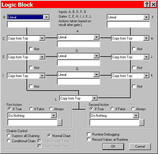
The Logic Block Event is a bit complicated and may take some getting used to. It allows rather complex conditional tests and provides a method of performing miscellaneous actions or tasks that are not available in the standard events.
The event dialog consists of seven parts:
- Five input blocks. What to test.
- Seven Logic Gates. What questions to ask.
- Six Not Gates.
- Twelve Named values.
- Two Actions. What to do, based on answer.
- Chain control.
- Runtime Debugging control.
- Record Values at Runtime control.
Input blocks.....
Each of the five input blocks can be configured independently to extract information from the current state of the game or to provide a constant literal value to be compared with other inputs. Each input has a text field that can be used to provide further information about what data you want.
For example, you might wish to know if there are at least three members in the current party. You could configure input-B as "Party Size", configure input-A as "Literal" with the number 2 in its text field, and configure Gate-C as "Arithmetic Greater". The output of Gate-C would be true if the party size was three or more.
Logic Gates
Each of the Logic Gates is identical. Each is a two-input device that can be configured to produce outputs that depends on one or both of the inputs. The output can be a logic value (True or false), a number, or a string of characters. In actuality, the output is always a string of characters. Truth is represented by "1", false is represented by "", and numbers are represented by decimal digits.
For example, you might wish to know if a global attribute named "Diploma" has the value "Giddeon". You could do this by fetching the global attribute using input-B, providing the literal "Giddeon" from input-A, and configuring Gate-C with the function "String Equal". The output of Gate-C would then be either "1" or "" depending on whether the global attribute was or was not exactly "Giddeon".
The gates have an input from the top and an input from the side. When the operation is not commutative (such as "Arithmetic minus") then the top input is considered the "left" operand and the side input is considered "right". For example, the Gate labeled 'K' has an input on the top from Gate-J and an input from the side (its left side) form the 'raw' input labeled 'G'. If this gate specified 'Arithmetic Minus' then the result would be Gate-J minus Input-G.
Not Gates
Six of the Logic Gates have outputs that pass through "Not" gates. Enabling a Not Gate causes the truth value to be toggled between true and false. Any non-blank value is considered true and is turned into a blank (or empty) string and any empty string is considered false and turned into the string consisting of the single digit "1". When not enabled, the Not Gates have no effect whatsoever.
Named Values
The lines emanating from the five inputs and from the seven logic gates represent values that you can reference in the parameter text of other inputs and actions. This is done in the text fields using the ampersand character. For example, let us say you want to set a global attribute to be the name of a party member so that you can talk about him later when he is no longer a part of the party. You could configure input-A to "Character Name". Then you might configure the first action field to "Set Global Attribute". The parameter text of the Action field might be "Member=&A". This would mean that the global attribute named "Member" would have the value of the line leaving the input labeled "A"; in this case the character's name. You should note that enabling the 'Not' gate on a line does not modify the Named Value associated with that line.
The values associated with the twelve lines are computed on alphabetical order. So, for example, it would not make sense to reference Line-E in the parameter text of Input-A. If you did, it would be the empty string.
Actions
There are two actions that can be performed as a result of this event. Each can be configured to occur unconditionally or only if the result of the computation of Gate-L is true or false. The text field of the parameters can reference named values. See the paragraph describing "Named Values".
Chain Control
Chaining can be totally disabled, set to "normal Chain", or can be configured to chain based on the result of the computation of Gate-L.
"Normal Chain" means to use the settings from the Event Viewer to determine whether or not chaining occurs. For example, chain if event happens.
"Chain if True" and "Chain if False" provide a way to go in two different directions depending on the results of the computation. For example, you might want to chain to a combat event if there are fewer than three characters in the party or to a text event otherwise. You should set "Conditional Chain", "Chain if True", and "Chain if False". Then in the event viewer you should add chained events to the "True" and "False" branches of the "Logic Block" event.
Runtime Debugging Control
Turning on Runtime Debugging will cause the results of each Input and Gate to be written to the log file. This can be very handy if things do not seem to be working as designed. There are many ways to make mistakes.
Record Values at Runtime
Enabling this control causes all the values labeled "A" through "L" to be recorded for later use in GPDL scripts. The recording takes place after all the values have been computed but before any actions are processed. This means that GPDL scripts in the input blocks that reference these recorded values will get the values from the previous LOGIC_BLOCK event that recorded the values and GPDL scripts in the action blocks will get the values from the current LOGIC_BLOCK (if recording is enabled).
The GPDL function '$LOGIC_BLOCK_VALUE' can be used to retrieve these values.
Control Flow
This diagram shows how the flow of control works it's way through the LogicBlock event, and how inputs and gates are combined into a final result.
Inputs: A, B, D, F, G
Gates: C, E, H, I, J, K, L

   // gather inputs
   w0 = inputA
   w1 = inputB
   w3 = inputD
   w5 = inputF
   w6 = inputG

   //
   // perform left side computations
   //
   w2 = gateC(w0,w1)
   w12 = not(w2)

   w4 = gateE(w3,w12)
   w13 = not(w4)

   w8 = gateI(w6,w13)
   w15 = not(w8)

   //
   // perform right side computations
   //
   w7 = gateH(w5,w0)
   w14 = not(w7)

   w9 = gateJ(w3,w14)
   w16 = not(w9)

   w10 = gateK(w6,w16)
   w17 = not(w10)

   //
   // combine left and right sides using Gate L
   //
   w11 = gateL(w15,w17)

	w1			w5
	|			|
	w2<------ w0 ---------->w7
	|			|
	w12			w14
	|			|
	w4<------ w3 ---------->w9
	|			|
	w13			w16
	|			|
	w8<------ w6 ---------->w10
	|			|
	w15			w17
	|			|
	|			|
	|-------->w11<----------|
		   |
	   Action1---Action2  // take action(s) based on result of w11
Logic Block Inputs | Logic Block Values | Logic Block Gates | Logic Block Actions